Joule Thief (Advanced Variations)
by Community-developed
Safety & Liability Disclaimer
Replicating alternative electromagnetism or mechanical resonance systems carries extreme physical hazards including lethal voltage shock, explosive gas ignition, mechanical shrapnel, and chemical toxicity. All contents, schematics, and guidelines on this page are provided strictly for educational and historical research.
Device-Specific Hazards:
Very safe — low voltage.
By viewing or constructing any design herein, you agree to assume 100% of all risks and to indemnify and hold harmless the site owners, authors, and contributors. Read our complete, legally binding Safety & Liability Disclaimer.
Overview
A minimalist blocking oscillator circuit that boosts voltage from a 'dead' battery (below 1V) to light an LED. The basic circuit uses just 5 components. Advanced variants include MOSFET-driven versions and multi-stage cascades. The basic Joule Thief is a legitimate, well-understood boost converter. Patrick Kelly recommends it as the very first project for newcomers.
⚖️ What Would Convince Us?
To validate the anomalies claimed for this device under mainstream scientific parameters, builders and inventors must document and present evidence satisfying the following criteria:
Accurate RMS power integration of high frequency pulses
Chemical battery capacity degradation curves showing total energy conservation
Continuous output power measurement matching standard inductor formula
Investigation & Credibility Metrics
Direct inventor writings, patents, or lab notebooks available.
Effect matches accepted physics (e.g. basic inductance, ion wind).
Replicated and validated by multiple independent builders.
Oscilloscopes and power analyzers used to record transient waveforms.
This device is purely open-source or historical; no active sales.
Community Status
Kelly recommends as first project. Teaches fundamental concepts (inductor collapse, voltage boost, oscillation) needed for every other device on this list.
🔧 Build Guides
⚠️ CRITICAL SAFETY WARNING
DANGER: LETHAL VOLTAGE, EXPLOSIVE GASES, AND HIGH-VELOCITY PROJECTILES.
This document is a historical archive of unverified claims, NOT a set of instructions. Enmagx and its creators take zero responsibility for injury, death, or property damage resulting from attempting to replicate these theoretical devices.
Proceed for historical research purposes only. Do not attempt to build without professional engineering supervision.
📺 Video & External References
How a Joule Thief Works & Construction Tutorial
🔗 Step-by-Step Construction Guides & Forums
📖 Patrick Kelly Guide: Technical Assessment
Chapter 12 REFERENCE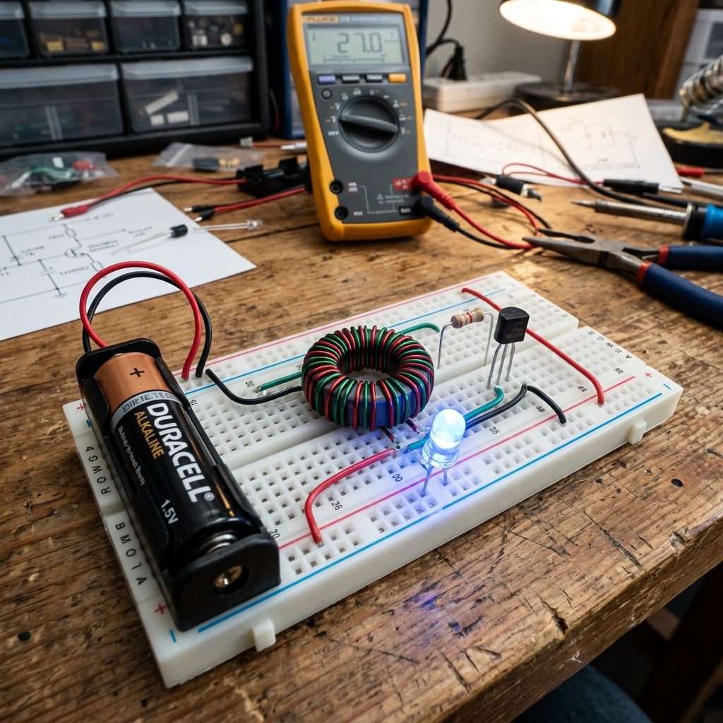 Figure: Joule Thief (Advanced Variations) schematic layout from Patrick Kelly\'s Guide
⚠️ Unverified or Disputed Media Archive
The following media assets associated with this device have low verification confidence, lack clear copyright licensing, are AI-generated, or are contextually disputed.
🤖 AI GENERATEDHistorical rendering of the joule-thief.
Reported Source: Local Generated Media Archive
License: FAIR_USE (COMMENTARY_ONLY)
Discussions
View all →No discussions yet. Be the first to start one!
🔧 Key Components
- •Small ferrite toroid core
- •NPN transistor (2N2222 or similar)
- •1kΩ resistor
- •LED
- •Magnet wire (two lengths)
⚠️ Safety
Very safe — low voltage.
Categories
🛠️ Construction Manual
A complete, step-by-step replication manual is available for this device. Sourced from public archives.
📥 Download Full Manual (PDF)🏛️ Historical Forum Archive
Preserved threads from the legacy Overunity.com community relating to this device:
📖 Patrick Kelly Guide
The complete chapter reference text and schematic diagram are embedded directly in the main section of this page.