Bob Boyce High-Efficiency Electrolyzer
by Bob Boyce · USA
Safety & Liability Disclaimer
Replicating alternative electromagnetism or mechanical resonance systems carries extreme physical hazards including lethal voltage shock, explosive gas ignition, mechanical shrapnel, and chemical toxicity. All contents, schematics, and guidelines on this page are provided strictly for educational and historical research.
Device-Specific Hazards:
Produces HHO gas (hydrogen-oxygen mixture) — extremely explosive. Flash arrestor is mandatory. Never use near open flames. Adequate ventilation essential.
By viewing or constructing any design herein, you agree to assume 100% of all risks and to indemnify and hold harmless the site owners, authors, and contributors. Read our complete, legally binding Safety & Liability Disclaimer.
Overview
A 101-plate series-cell electrolyzer driven by a triple-oscillator board (PWM3) through a custom toroidal transformer. The three overlapping frequencies create a complex waveform that resonates with the water cell, achieving claimed hydrogen production rates 150-200% of the Faraday electrolysis limit.
⚖️ What Would Convince Us?
To validate the anomalies claimed for this device under mainstream scientific parameters, builders and inventors must document and present evidence satisfying the following criteria:
Independent gas flow meter calibration
Full input RMS power analysis capturing high frequency harmonics
Calorimetric verification of cell operating temp
Investigation & Credibility Metrics
Derived historical books, catalog indexes, or compiled archives.
Claimed overunity/propulsion has not been verified in a control lab.
Sub-components work, but operational COP > 1 has not been replicated.
Oscilloscopes and power analyzers used to record transient waveforms.
This device is purely open-source or historical; no active sales.
Community Status
The most sophisticated open-source electrolyzer design. PWM3 schematics freely shared by community. Plate conditioning process (involving systematic voltage cycling) is considered critical for performance.
🔧 Build Guides
⚠️ CRITICAL SAFETY WARNING
DANGER: LETHAL VOLTAGE, EXPLOSIVE GASES, AND HIGH-VELOCITY PROJECTILES.
This document is a historical archive of unverified claims, NOT a set of instructions. Enmagx and its creators take zero responsibility for injury, death, or property damage resulting from attempting to replicate these theoretical devices.
Proceed for historical research purposes only. Do not attempt to build without professional engineering supervision.
📺 Video & External References
🔗 Step-by-Step Construction Guides & Forums
The official step-by-step guide for plate cross-sanding, cleaning, KOH conditioning, and PWM3 tuning.
Archived patent transcripts, toroidal coil winding guides, and safety flash arrestor diagrams.
📖 Patrick Kelly Guide: Technical Assessment
Chapter 10 REFERENCE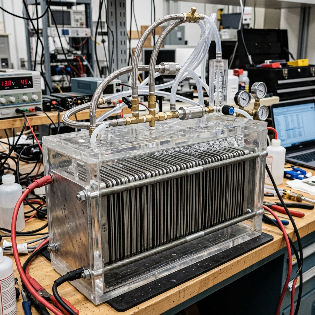 Figure: Bob Boyce High-Efficiency Electrolyzer schematic layout from Patrick Kelly\'s Guide
⚠️ Unverified or Disputed Media Archive
The following media assets associated with this device have low verification confidence, lack clear copyright licensing, are AI-generated, or are contextually disputed.
🤖 AI GENERATEDHistorical rendering of the boyce-electrolyzer.
Reported Source: Local Generated Media Archive
License: FAIR_USE (COMMENTARY_ONLY)
Discussions
View all →No discussions yet. Be the first to start one!
🔧 Key Components
- •101 × 316L stainless steel plates (precisely prepared/conditioned)
- •Triple oscillator board (PWM3e or PWM3f)
- •Custom toroidal transformer
- •NaOH or KOH electrolyte
- •Acrylic cell housing
- •Hose barbs and tubing
- •Flash arrestor (safety critical)
⚠️ Safety
Produces HHO gas (hydrogen-oxygen mixture) — extremely explosive. Flash arrestor is mandatory. Never use near open flames. Adequate ventilation essential.
Categories
🛠️ Construction Manual
A complete, step-by-step replication manual is available for this device. Sourced from public archives.
📥 Download Full Manual (PDF)📖 Patrick Kelly Guide
The complete chapter reference text and schematic diagram are embedded directly in the main section of this page.