Bedini SSG Motor/Energizer
by John Bedini · USA · ~1984
Safety & Liability Disclaimer
Replicating alternative electromagnetism or mechanical resonance systems carries extreme physical hazards including lethal voltage shock, explosive gas ignition, mechanical shrapnel, and chemical toxicity. All contents, schematics, and guidelines on this page are provided strictly for educational and historical research.
Device-Specific Hazards:
Low voltage system (12V). Standard electronics safety. Ensure proper heatsinking of transistor.
By viewing or constructing any design herein, you agree to assume 100% of all risks and to indemnify and hold harmless the site owners, authors, and contributors. Read our complete, legally binding Safety & Liability Disclaimer.
Overview
A monopole pulse-motor/energizer using a rotor with permanent magnets passing by a bifilar coil, triggering transistor-based pulse charging of secondary batteries. The high-voltage back-EMF spikes ('radiant energy') from collapsing magnetic fields are directed into a charging battery through a diode. Primarily explored for battery desulfation and rejuvenation of dead lead-acid batteries. Battery desulfation is a real, documented electrochemical phenomenon.
⚖️ What Would Convince Us?
To validate the anomalies claimed for this device under mainstream scientific parameters, builders and inventors must document and present evidence satisfying the following criteria:
Closed-loop self-running operation without external batteries
Calorimetric verification of net energy output
Calibrated input power measurement matching output power factor
Investigation & Credibility Metrics
Direct inventor writings, patents, or lab notebooks available.
Effect matches accepted physics (e.g. basic inductance, ion wind).
Replicated and validated by multiple independent builders.
Oscilloscopes and power analyzers used to record transient waveforms.
This device is purely open-source or historical; no active sales.
How It Works
When a rotor magnet passes the coil, the trigger winding induces base current in the transistor, turning it on. Current flows through the power winding creating an electromagnet that repels the rotor magnet. When the magnet passes, the transistor turns off and the collapsing magnetic field generates a high-voltage spike (back-EMF) that is captured through a diode into the charging battery. The neon bulb protects the transistor from excessive voltage.
History & Background
John Bedini developed this technology over decades, demonstrating it at multiple Energy Science & Technology Conferences. The SSG became the #1 recommended starter project in the community after Bedini released simplified build plans. The 'Bedini SG - The Complete Beginner's Handbook' was published through Energetic Forum's community. Over a thousand builds have been documented across Instructables, YouTube, and dedicated forums.
Community Status
THE most replicated device in the entire alternative energy community. Battery desulfation effects are widely confirmed. COP > 1 remains debated but the device is universally recommended as the entry point for newcomers.
📏 Measurement Notes
Standard multimeters are insufficient for measuring the high-voltage, short-duration back-EMF spikes. An oscilloscope is essential. Battery state-of-charge must be measured over complete charge/discharge cycles, not instantaneous voltage readings. Battery voltage 'recovery' after load removal is normal chemistry, not energy gain.
🔧 Build Guides
⚠️ CRITICAL SAFETY WARNING
DANGER: LETHAL VOLTAGE, EXPLOSIVE GASES, AND HIGH-VELOCITY PROJECTILES.
This document is a historical archive of unverified claims, NOT a set of instructions. Enmagx and its creators take zero responsibility for injury, death, or property damage resulting from attempting to replicate these theoretical devices.
Proceed for historical research purposes only. Do not attempt to build without professional engineering supervision.
📺 Video & External References
Bedini SSG Monopole Motor Build & Operation Demonstration
🔗 Step-by-Step Construction Guides & Forums
Complete step-by-step written tutorial with high-resolution workbench photographs.
The largest community discussion forum containing decades of replication troubleshooting.
Moderated research forum overseen by Aaron Murakami containing advanced tuning logs.
📖 Patrick Kelly Guide: Technical Assessment
Chapter 5 REFERENCE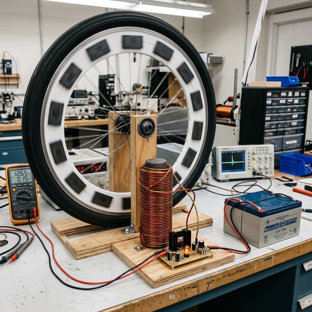 Figure: Bedini SSG Motor/Energizer schematic layout from Patrick Kelly\'s Guide
⚠️ Unverified or Disputed Media Archive
The following media assets associated with this device have low verification confidence, lack clear copyright licensing, are AI-generated, or are contextually disputed.
🤖 AI GENERATEDHistorical rendering of the bedini-ssg.
Reported Source: Local Generated Media Archive
License: FAIR_USE (COMMENTARY_ONLY)
Discussions
View all →No discussions yet. Be the first to start one!
🔧 Key Components
- •Bicycle wheel or rotor disc
- •Ceramic ferrite magnets (1" x 2" x 3/8")
- •Bifilar coil: #23 AWG (power) + #26 AWG (trigger) wound together
- •Core: bundle of 1/16" soft iron welding rods
- •MJL21194 NPN transistor
- •1N4007 diodes
- •1kΩ potentiometer (2W)
- •470Ω 1W resistor
- •NE-2 neon bulb
- •Heatsink
- •Two lead-acid batteries (run + charge)
📄 Patents
⚠️ Safety
Low voltage system (12V). Standard electronics safety. Ensure proper heatsinking of transistor.
Categories
🛠️ Construction Manual
A complete, step-by-step replication manual is available for this device. Sourced from public archives.
📥 Download Full Manual (PDF)🏛️ Historical Forum Archive
Preserved threads from the legacy Overunity.com community relating to this device:
📖 Patrick Kelly Guide
The complete chapter reference text and schematic diagram are embedded directly in the main section of this page.